Serial Communication
The 3-pin serial port (a 2.5mm jack) on your Classpad allows it to communicate with other devices, such as a PC for transferring programs or another microcontroller (like an ESP32 or Arduino) for custom hardware projects. This guide covers several methods for creating the necessary connection.
Important Note on Voltage Levels
Section titled “Important Note on Voltage Levels”Before you begin, it’s critical to understand the voltage levels of the serial interface.
- Modern Classpads (like the fx-CP400 / Classpad II) use 3.3V logic.
- Many microcontrollers (like the Arduino Uno) use 5V logic.
- Older calculators (like the Classpad 300) used a higher voltage (~4V).
Connecting a 5V device’s Transmit (TX) pin directly to a 3.3V calculator’s Receive (RX) pin can damage the calculator. To safely connect them, you must use a voltage divider or a logic level shifter to step the 5V signal down to 3.3V.
A common voltage divider consists of two resistors (e.g., 10kΩ and 20kΩ) to reduce the voltage. The ESP32 and ESP8266 are 3.3V devices, so they can be connected directly without a voltage divider.
Method 1: Building a PC-to-Calculator Cable (from Scratch)
Section titled “Method 1: Building a PC-to-Calculator Cable (from Scratch)”This method uses common, inexpensive electronic components to build a USB-to-Serial cable for connecting your calculator to a PC.
Thanks to Calamari for the original guide.
Parts Required
Section titled “Parts Required”- CH340G USB to TTL Adapter
- DuPont Cables (Male-to-Female)
- 3.5mm Connector to Screw Terminal
- 3.5mm Female to 2.5mm Male Stereo (TRS) Adapter
- Recommended: USB 2.0 Extension Cable
Tools Required
Section titled “Tools Required”- #0 Phillips Screwdriver
- Knife for trimming plastic
Assembly Instructions
Section titled “Assembly Instructions”- Set Voltage Jumper: On the CH340G adapter, move the jumper from the
5V - VCCposition to theVCC - 3V3position. This sets the logic level to 3.3V, which is safe for the calculator. - Connect DuPont Cables: Connect three female DuPont cables to the
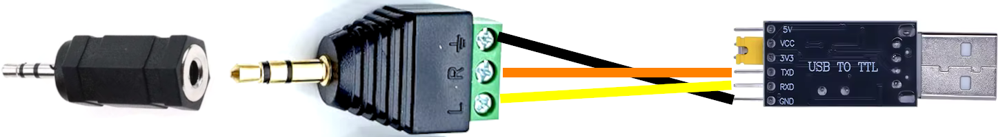
GND,TXD, andRXDpins on the USB adapter. - Wire the Terminal: Using the screwdriver, connect the male ends of the DuPont cables to the 3.5mm screw terminal:
GNDpin (USB adapter) →⏚(Ground) terminal.TXDpin (USB adapter) →R(Ring) terminal.RXDpin (USB adapter) →L(Tip) terminal.
- Connect Adapters: Plug the 3.5mm terminal into the 3.5mm-to-2.5mm adapter.
Trimming the Adapter
Section titled “Trimming the Adapter”The 2.5mm port on the calculator is often recessed. The plastic housing on the adapter may be too wide to fit. Carefully use a knife to shave away the excess black plastic near the metal tip until it can be fully inserted into the calculator.
For a picture of the completed cable, see this post on Planet-Casio.
Method 2: Modifying an Existing Casio Cable
Section titled “Method 2: Modifying an Existing Casio Cable”If you have an official Casio SB-62 cable or another 2.5mm audio cable, you can cut it and wire it to a USB-to-TTL module.
Thanks to Lize for this guide.
Parts & Tools Required
Section titled “Parts & Tools Required”- An existing 2.5mm cable (like the SB-62 or a headphone cable)
- A USB-to-TTL module (e.g., PL2303, CP2102, FT232)
- Wire stripper (or scissors)
- Soldering iron and solder
- Heat shrink tubing or electrical tape
- Three DuPont wires
Assembly Steps
Section titled “Assembly Steps”-
Cut the Cable: Cut your 2.5mm cable, leaving enough length to work with.
-
Strip Wires: Carefully strip the outer insulation to expose the inner wires. You should find a ground wire (often braided copper) and two insulated data wires (for Tip and Ring).
-
Prepare Wires: Twist the ground wire into a single strand. Strip a small amount of insulation from the two data wires. “Tin” all three wires by applying a small amount of solder to them.
-
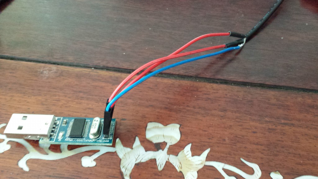
Solder Connections: Solder the three prepared DuPont wires to the three wires from your 2.5mm cable. It’s best to use different colored DuPont wires to keep track of them. Use heat shrink tubing or electrical tape to insulate each connection.
-
Connect to TTL Module: Plug the DuPont wires into your USB-to-TTL module. The connections must be crossed over:
- Cable Ground →
GNDpin on the module. - Cable Tip (Receive) →
TXD(Transmit) pin on the module. - Cable Ring (Transmit) →
RXD(Receive) pin on the module.
Note: If the connection doesn’t work, the most likely issue is that the TX/RX wires are swapped. Simply switch the two data wires on the TTL module’s pins.
- Cable Ground →
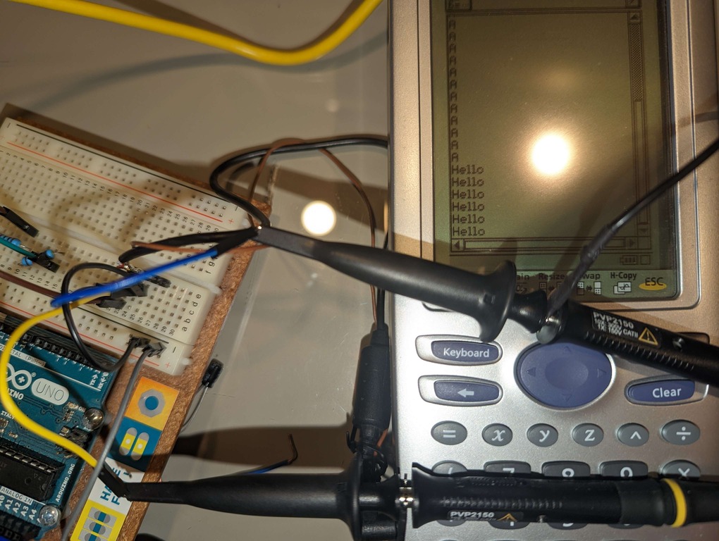
Method 3: Connecting to a Microcontroller (ESP32)
Section titled “Method 3: Connecting to a Microcontroller (ESP32)”You can connect your calculator directly to a microcontroller like an ESP32 to send and receive data, creating custom hardware projects.
Parts Required
Section titled “Parts Required”- ESP32 Development Board
ESP32-DEVKITC-32E - 2.5mm 4-Conductor Cable Assembly
CA-254S - 2x AA Battery Holder with Leads
23-BH2-3
Wiring Diagram
Section titled “Wiring Diagram”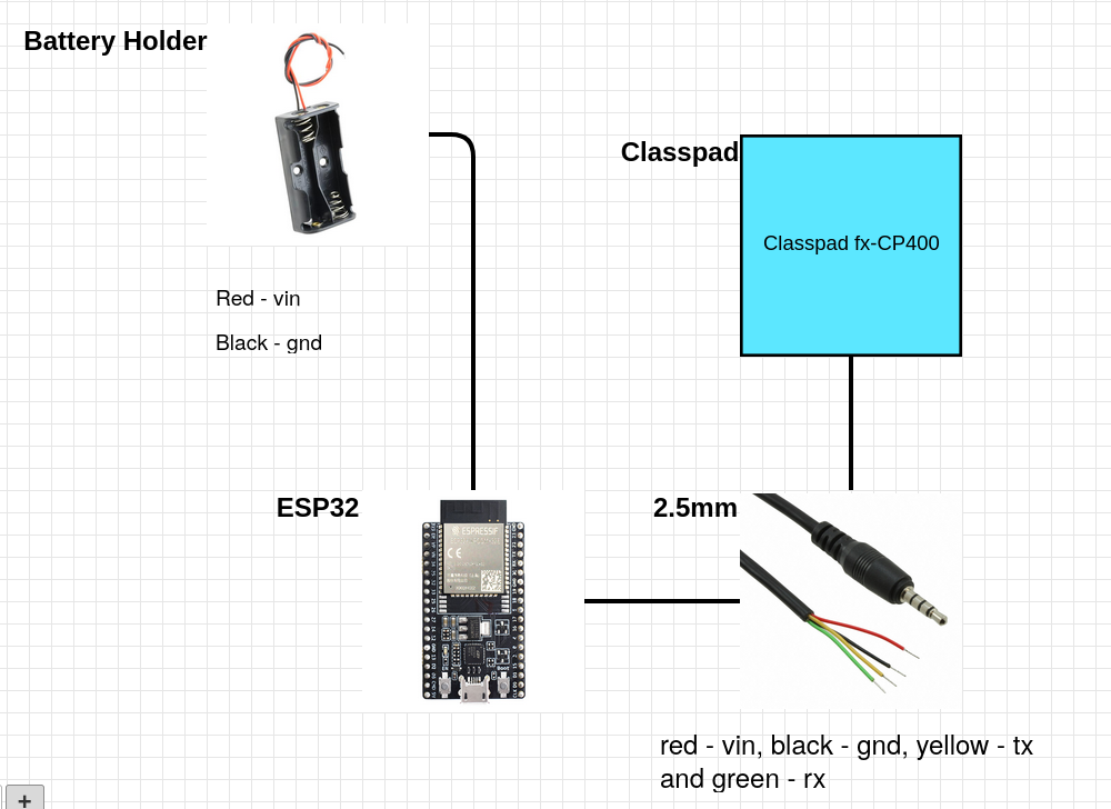
Wiring Instructions
Section titled “Wiring Instructions”- Power the ESP32: Connect the battery holder to the ESP32.
- Red wire (Battery Holder) →
VINpin on the ESP32. - Black wire (Battery Holder) →
GNDpin on the ESP32.
- Red wire (Battery Holder) →
- Connect ESP32 to 2.5mm Cable: The 2.5mm cable has four wires. The principle is to cross the transmit (TX) and receive (RX) lines.
- Cable Black wire (GND) →
GNDpin on the ESP32. - Cable Yellow wire (TX) → An RX pin on the ESP32 (e.g.,
RX2). - Cable Green wire (RX) → A TX pin on the ESP32 (e.g.,
TX2). - The red wire on the cable is unused in this setup.
- Cable Black wire (GND) →
- Connect to Calculator: Plug the 2.5mm jack into the calculator’s serial port.
Communicating with Casio BASIC
Section titled “Communicating with Casio BASIC”Hollyhock gives you full, low-level control over the serial port. However, you can also communicate with a standard, unmodified calculator running a Casio BASIC program using the SendVar38k and GetVar38k commands.
This makes it possible for a Hollyhock program on one calculator to communicate with a Casio BASIC program on another.
For a detailed breakdown of the protocol and a sample BASIC chat program, see the full documentation here: SendVar38k Protocol Details